 1.
1.
 2.
2.
 3.
3. 4.
4.
 5.
5.
 6.
6.
 7.
7.
 8.
8.
 9.
9.
 10.
10.
 11.
11.
 12.
12.
 13.
13.
 14.
14. Eric's Wheel
15.
15.
|
|
1.
|
2.
|
3. |
4.
|
5.
|
|
6.
|
7.
|
8.
|
9.
|
10.
|
|
11.
|
12.
|
13.
|
14. |
Eric's Wheel
15. |
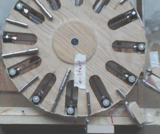
If I leave an opening in the rotor to avoid the dreaded flux lock my only hope for full rotation would be enough momentum to move the rotor through the gap or use a series of rotors. I don't think there is much torque since the motion is pulsing.
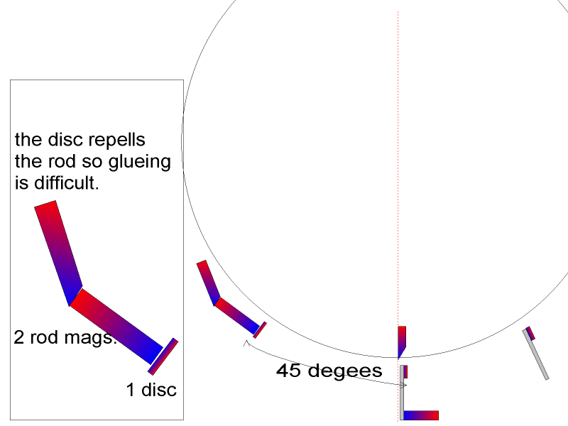
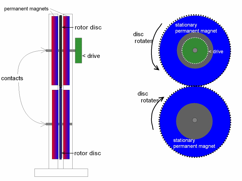
Aug26/04 I added a second stator disc with one ring magnet(piston) in between attempting to attract two magnets simultaneously, one to each disc.
Sept7/04 The pulse motion could be smoothed out by adding an extra wheel (wheels) mounted on a common axle. The torque might be increased by adding more discs to the stator 180 degrees from the existing ones. Magnets are added to the rotor magnets to balance the forces of so the rotor will continue to pulse to the next magnet.
Sept7/04 Because of the pulsing, I believe there will be no "flux lock" since each magnet is acting individually.
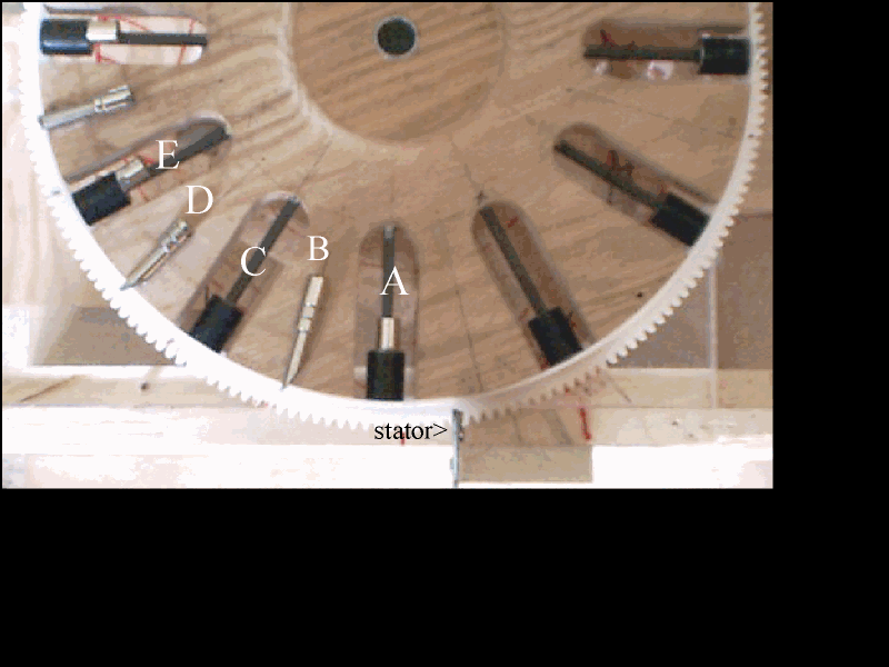
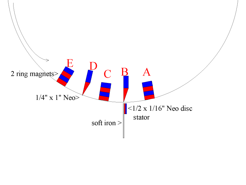
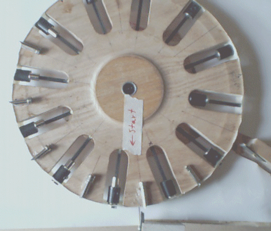
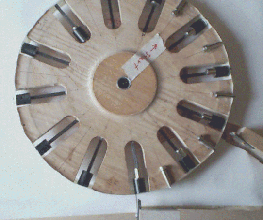
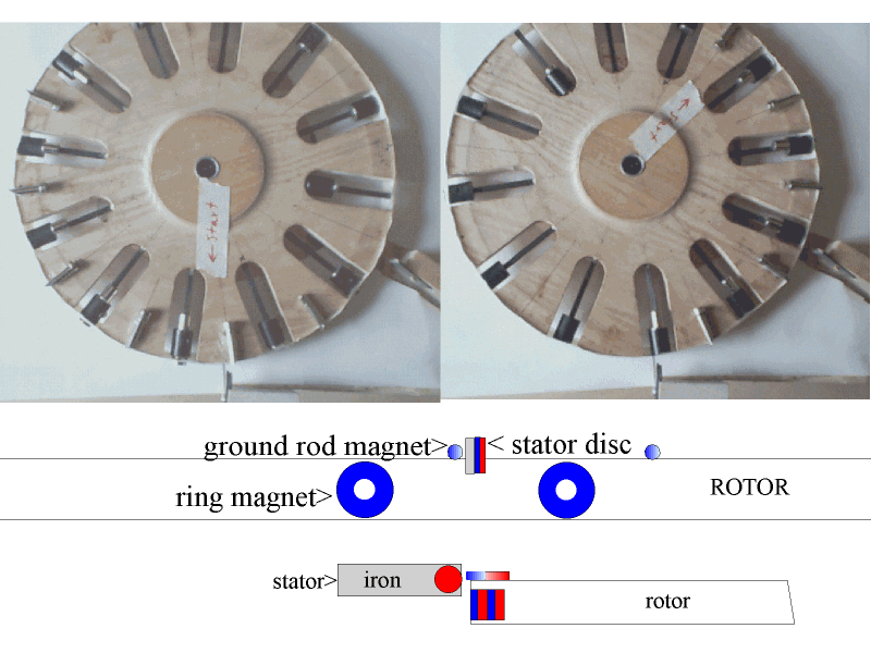
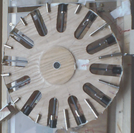
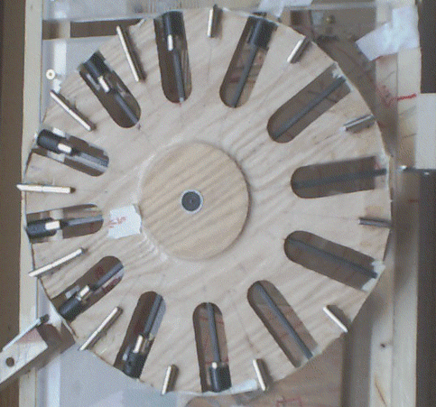
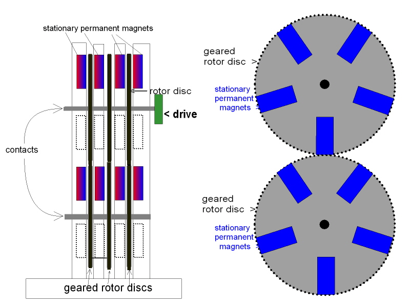
Sept11/04 After placing slanted magnets completely around the rotor I have found the dreaded "flux lock". Adding rotor discs on all sides slow down the rotor. Using 4 discs (figure 4disc.gif) smooths the motion of the rotor and seems to add torque. Adding magnets as per figure 4disc.gif also adds torque. To avoid the "flux lock" I have used 10 slanted magnets on the rotor, leaving an opening of 2 spaces. I still have 12 ring magnets in the rotor.
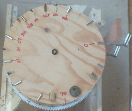
Sept12/04 Fig. 9 & 10. This configuration uses 2 discs as a stator 210 degrees apart and 4 ring magnets removed from the rotor. The rotor rotates 165-195 degrees consistantly. The motion is pulsing and appears to gain speed between 60 and 120 degrees of rotation.
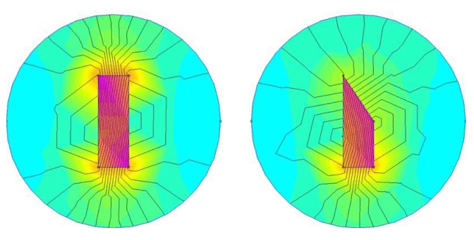
Sept14/04Fig. 7.I have added a magnet to the end of the iron of one stator. The added magnet seems to neutralize the attraction of the iron to the slanted magnet but the "kick by" of the ring magnet brings the slanted magnet forward.
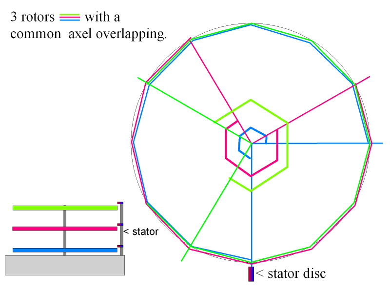
Fig.11 is a diagram of the proposed multi-rotor wheel.
Sept16/04 .The magnet(s) added to the stator iron seem to compensate for the orientation or proximity to iron of the wheel.
Sept30/04 .I started the multi-rotor wheel using the arrangment Fig.12as my bottom rotor. This setup attained 180 degrees of rotation. I have assembled a second rotor on the same axle and now have 285-300 degrees of rotation Fig.13.
Oct15/04 .I added a helper on the stator Fig.14. It increases the rotation to about 330degrees.
Oct15/04 . I have uploaded Eric Vogel's video. Compare the amount of kickback when using the repel force.
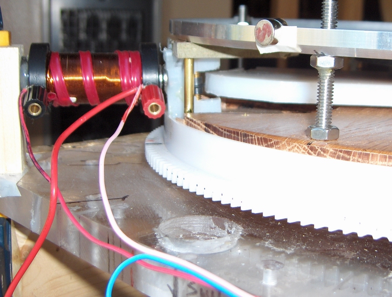
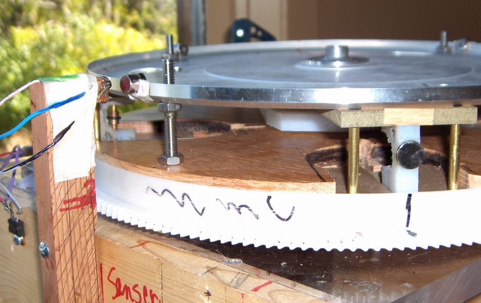
Pulse Motor |
video | rotor | wiring | pulse actuator | 9.6v pulse | |||||
| Wheel w/pulse | ||||||||||
| Dual C-generator | Multiple C-generator | Simple Motor drawing | Motor Video | Photo |
| 4 Piston Cam Wheel | ||||||
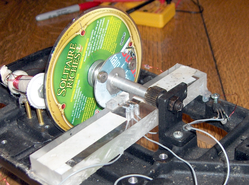
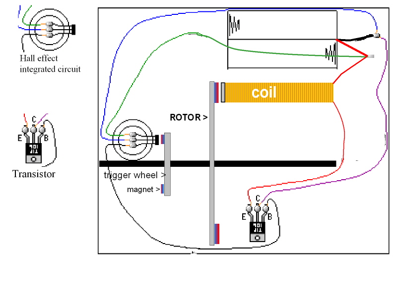
| 4 piston wheel video | Piston-Cam | Hall-effect IC | Detail drawing | Original wheel |
| Link to Magnet Piston Engine |